Relativity visualized

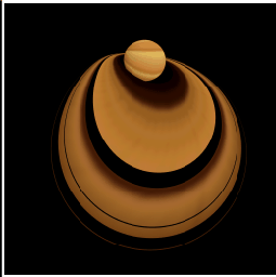
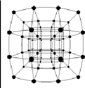
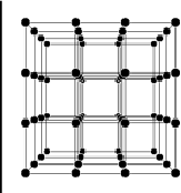
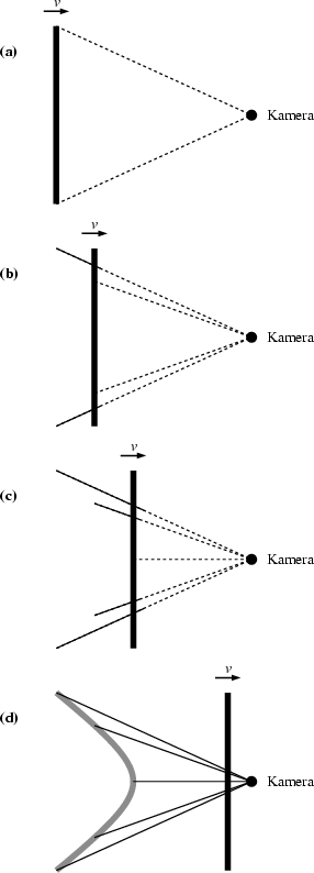
Strictly speaking, the statement that fast moving objects appear merely rotated is only correct when the objects are very far away. In the case of a close fly by, there will, in addition, be distortions. This is illustrated in Figure 6 using the planet Saturn as an example. The distortions can be illustrated especially clearly with an approaching three-dimensional lattice. (Figure 7). The bulging shape of the lattice planes is completely explained by light travel times. The case of a thin rod approaching a camera laterally demonstrates how (Figure 8). The rod is perpendicular to its direction of motion. The diagram shows five representative light rays that come from different points on the rod. The starting times have been computed in such a way that all five light rays reach the camera simultaneously. Since the rod continues to move in between the emission from the end points (Figure 8a) and the emission in the middle (Figure 8c), the emission points do not form a straight line but, as can be easily calculated, a hyperbola. A rod standing perpendicular to its direction of motion is seen as a hyperbola, a perpendicular plane, accordingly, appears as a hyperboloid.
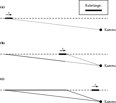
When comparing the moving and the non-moving lattices in Figure 7, another phenomenon besides the bulging of the lattice planes catches one's eye: The moving lattice appears to be lengthened in the direction of motion. This occurs in spite of the fact that in the direction of motion the lattice is length contracted. A measurement would show that the length in the direction of motion is only about 44% of the rest length. As explained in Figure 9, the apparent lengthening is also a consequence of the finite light travel times. Again, a thin rod approaches the camera. But this time the rod is aligned with the direction of motion. The diagram shows two light rays that start from the tip and the rear of the rod, respectively, and reach the camera at the same time. This is possible only if the light ray from the rear starts earlier (Figure 9a) than that from the tip (Figure 9b). Since the rod continues to move in the meantime, the two points of emission are farther apart than the (contracted) length of the rod. It is easy to check that they are even farther apart than the rest length of the rod.
Along the same lines one can establish that a rod moving away from the camera appears compressed in the direction of motion and that this compression is stronger than one would expect on the grounds of length contraction.
Contact: Would you like to send us a message?