There are different methods for the simulation of visual observations
in high speed flight. One of them is based on the aberration formula
and is in principle made up of the following steps:
Define an object by a number of points lying on its surface. This is
especially simple in the case of wire frame models.
They consist of lines each of which can be approximated by a polygon
connecting the specified points.
Specify camera velocity and viewing direction, choose at which point on
its path the camera is released.
For each of the specified surface points determine the angle θ
that a light ray from the point to the pinhole makes with the direction
of motion of the camera
(Figure 9).
The aberration formula gives the corresponding angle θ'
in the rest frame of the camera.
In the rest frame of the camera compute the point at which the light ray
hits the image plane. This depends on the direction of the incident ray
and on the orientation of the camera.
(For a camera that looks in the direction of motion, steps 3 and 4
can be replaced by computing the image point from the time of flight inside
the camera as explained in connection with
Figure 9.)
Construct the distorted look of the object from the image points.
In the case of wire frame models a polygon is drawn through the points
belonging to the same wire.
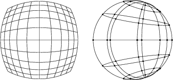
Figure 11
gives two examples. Simulations of wire frame models
permit to experiment with different kinds of objects
with comparatively short and simple computer codes.
Simulated looks of two wire frame models at 90% of the speed of light.
Left: The camera approaches a plane quadratic lattice, the viewing direction
is the direction of motion.
Right: The camera passes a sphere defined by lines of longitude
and circles of latitude, the viewing direction is perpendicular to the
direction of motion.
Authors: Ute Kraus,
Date: January 28, 2005
About Us.
Datenschutz.
All contents copyright (C) 2001-2023 Ute Kraus, Corvin Zahn. All rights reserved. For more information see Copyright.